Weekend hacking with gnuradio
Home easy or easy home?
I grabbed some rf controlled power-sockets called 'Easy Home' from our local discounter 'ALDI'.
The package contained 4 sockets + (just) one remote.
I went online and looked for some sort of USB dongle that could switch those sockets and found a very cheap one called 'Home Easy'.
You probably noticed that 'Easy Home' != 'Home Easy'. I did too, but somehow hoped that I could use the dongle off the shelf.
I was wrong.
The following describes my process towards a gnuradio module to print out the codes of the original remote and then re-using those codes with an USB dongle of a different vendor.
Used Hardware:
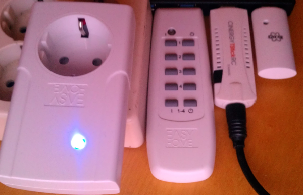
Easy Home (Sockets+Remote)
The 10 button remote allows on/off for all 4 sockets and has additional master-mode to on/off all of them at once.On power up, the socket is in 'learning mode'. It waits about 30 seconds to receive an 'on' signal that is then assumed to be the correct one and internally sets some sort of identifier.
If no signal is received during that time frame, the socket takes the last stored identifier.
A socket can be taught to listen to one or multiple on/off buttons. Pressing 'off' during learning mode removes the button from the socket. Pressing master-mode off, results in all stored code getting deleted.
Vendor: Globaltronics GmbH & Co KG
Socket-Model: GT-FSI-07
Remote-Model: GT-9000
RTL-SDR (USB DVB-T Receiver)
A DVB-T USB-dongle (tv-receiver) with an Elonics E4000 tuner that works as software defined radio for signal analysis.There is open source software available that allows setting a frequency, bandwidth and sample rate and get I/Q data as output.
Home Easy (USB-RF-Sender)
USB-dongle that can transmit on 433.92 MHz.Vendor: ROOS Electronics bv.
Model: ELRO AB600USB
idVendor=04d9, idProduct=1357
Manufacturer: ABLOCK
Guesswork, speculation and some luck
I used baudline in combination with rtl_sdr to take a deeper look:
sudo rtl_sdr -s 2e6 -f 433.92e6 - | baudline -reset -stdin
# This invokes rtl_sdr
# -s 2e6 sets the sample rate to 2000000 samples per second
# -f 433.92e6 sets the frequency to 433.92 MHz
# and then pipes the output into baudline
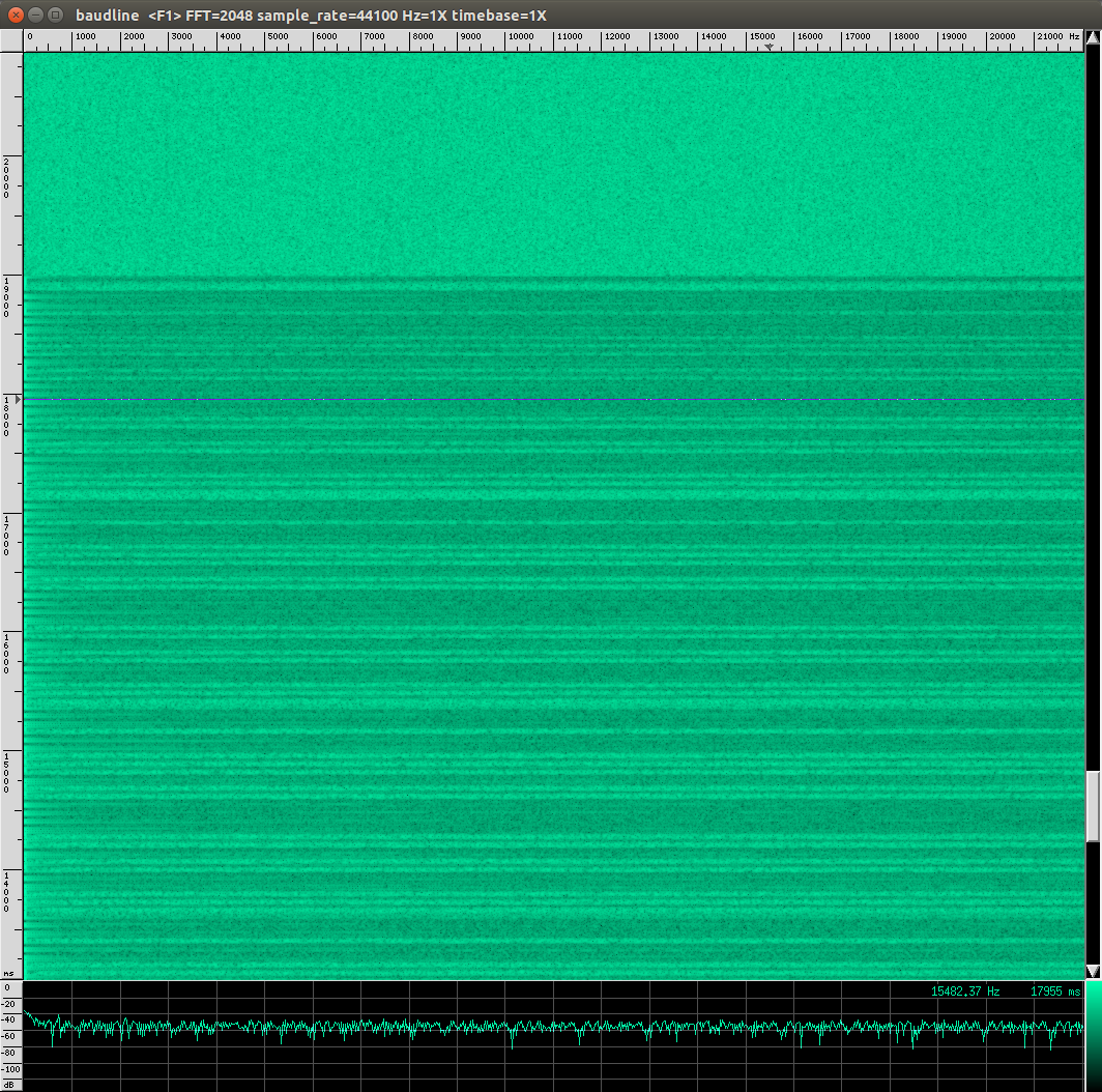
The output confirms my assumption. Once I press the button on my remote I can see 'stuff' passing through the histogram inside baudline.
Hint: You can stop the processing of new data with a right click and then selecting 'Pause'.
Looking into the options of baudline I spotted this parameter:
-quadrature Enable complex I/Q display analysis.
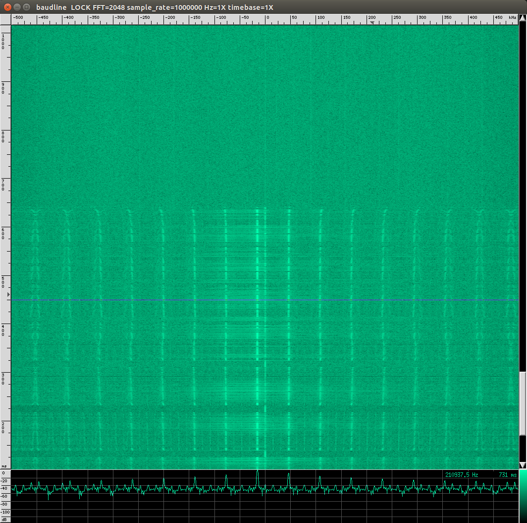
Since the output of the rtl_srd is I/Q data, I put that option on my 'try that' list. I also realized that I need to set the input format to unsigned int and then increased the baudline sample rate to 1e6.
sudo rtl_sdr -s 2e6 -f 433.92e6 - | baudline -reset -samplerate 1000000  -format u8 -quadrature -stdin
# This invokes rtl_sdr
# -s 2e6 (sets the sample rate to 2000000 samples per second)
# -f 433.92e6 (sets the frequency to 433.92 MHz)
# and then pipes the output into baudline
# -reset (use defaults)
# -samplerate 1000000 (guess what)
# -format u8 (unsigned integer as input)
# -quadrature (I/Q data is coming)
# -stdin (take input from stdin)
To get a better look at the signal I switched to the waveform display. (right click, then select displays, then waveform)
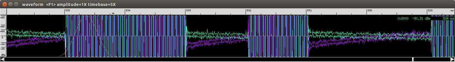
Using ALT+(Left/Right) allows to scale the time and reveals the data I am looking for:
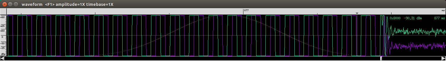
(the waveform without scaling)
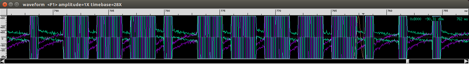
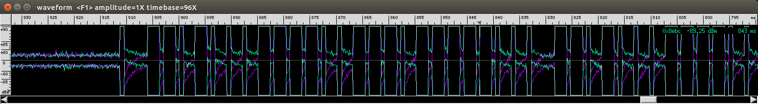
(scaling reveals something that looks like bits)
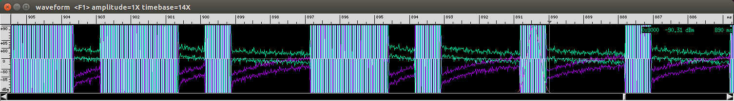
With some sample waveform images and the assumption that long blocks represent a binary one and that short blocks a binary zero, I was able to write down some binary codes for the buttons on my remote.
It is not visible in the pictures but some blocks are longer than the 'long blocks' and seem to mark the end of the code which repeats a few times.
One extracted code would be:
110100000111010000110000
At this point I did not bother to go into what those bits might mean. I only knew that that they all had the same prefix:
1101 which might address the model of socket and that the last 4 bits id one of the 5 button sets.
I also saw that there are multiple repeating codes for the same button.
With 10 buttons in total and a unknown number of codes per button I did not bother to obtain more samples manually. At this point I was more tempted to play with my new USB rf-sending device.
I made some notes about the duration of the signals, since I expected that information to be useful later.
A last hint about baudline: Use anything but the internal copy+paste option of baudline. I did not look into it, but there is a difference between original data and data stored by baudline.
If you want to work with samples, pipe them into a file and use dd to cut out the parts you need.
Learning, testing and success.
I was very happy to find some ready to use C++ code called he853-remote that allowed me to send some initial signals with that new hardware.
The code is quite easy to read.
It uses 'HIDAPI' (libusb). Obtains a handle to the device via vendor and product id and then sends bytes to it.
The original code fills an array uint8_t rfCmdBuf[32] with data and passes it in chunks of 8 bytes to HE853Controller::sendOutputReport(uint8_t* buf) which prepends one null byte and sends those 9 bytes to the device. After those 4 blocks, the code sends a special block (also 9 bytes) to the device to trigger the sending.
Looking at the inline documentation and doing some correlation between what I do and what I can observe via baudline, I created a version of rfCmdBuf that works with my socket:
// Frame number 1
rfCmdBuf[0*8+0] = 0x01;
// StartBit_HTime
rfCmdBuf[0*8+1] = (uint8_t) ((420 / 10) >> 8);
rfCmdBuf[0*8+2] = (uint8_t) (420 / 10);
// StartBit_LTime
rfCmdBuf[0*8+3] = (uint8_t) ((2200 / 10) >> 8);
rfCmdBuf[0*8+4] = (uint8_t) (2200 / 10);
// EndBit_HTime
rfCmdBuf[0*8+5] = (uint8_t) ((6200 / 10) >> 8 ); // set to 0 for learning mode
rfCmdBuf[0*8+6] = (uint8_t) (6200 / 10); // set to 0 for learning mode
// EndBit_LTime
rfCmdBuf[0*8+7] = 0x00;
// Frame number 2
rfCmdBuf[1*8+0] = 0x02;
// EndBit_LTime
rfCmdBuf[1*8+1] = 0x00;
// DataBit0_HTime
rfCmdBuf[1*8+2] = (uint8_t) (330 / 10); // 2250
// DataBit0_LTime
rfCmdBuf[1*8+3] = (uint8_t) (1190 / 10); // 750
// DataBit1_HTime
rfCmdBuf[1*8+4] = (uint8_t) (1190 / 10); // 750
// DataBit1_LTime
rfCmdBuf[1*8+5] = (uint8_t) (330 / 10); // 2250
// DataBit_Count
rfCmdBuf[1*8+6] = (uint8_t) 24; // how many bits to send
// Frame_Count
rfCmdBuf[1*8+7] = (uint8_t) 4;
// Frame number 3
rfCmdBuf[2*8+0] = 0x03;
// payload: 110100000111010000110100
rfCmdBuf[2*8+1] = 0xd0; // 11010000
rfCmdBuf[2*8+2] = 0x74; // 01110100
rfCmdBuf[2*8+3] = 0x34; // 00110000
rfCmdBuf[2*8+4] = 0x00;
rfCmdBuf[2*8+5] = 0x00;
rfCmdBuf[2*8+6] = 0x00;
rfCmdBuf[2*8+7] = 0x00;
// Frame number 4
rfCmdBuf[3*8+0] = 0x04;
rfCmdBuf[3*8+1] = 0x00;
rfCmdBuf[3*8+2] = 0x00;
rfCmdBuf[3*8+3] = 0x00;
rfCmdBuf[3*8+4] = 0x00;
rfCmdBuf[3*8+5] = 0x00;
rfCmdBuf[3*8+6] = 0x00;
rfCmdBuf[3*8+7] = 0x00;
Which results into this sequence of 5*9 bytes:
00 01 00 2A 00 DC 02 6C 00
00 02 00 21 77 77 21 18 01
00 03 D0 74 34 00 00 00 00
00 04 00 00 00 00 00 00 00
00 05 00 00 00 00 00 00 00
The initial task is solved. I'm now able to switch the sockets with that USB device from a different vendor. But it somehow nagged me that I would have to collect the codes manually, so I went a bit further to learn about gnuradio and how to write modules for it.
The extra mile - a special decoder
There is a nice GUI (gnuradio-companion) to draft the radio. That view transforms into python which can be manipulations if needed.
There are many guides on how to install and setup. Most of them advice you to use the latest and greatest version available. I give you the same advice. Compile from source. Since you need a working build environment to write own modules, it does make sense to have the 'normal' setup in place.
I checked a basic introduction into gnuradio and have to say that I am unfamiliar with most of its components since I miss the RF background.
But that did not stop me from having some fun with it.
At the beginning I tested what the components do by attaching GUI elements like a scope or histogram to them. This gave me at least a rough idea on the possibilities and if the components really do what I expect them to do.
After playing a bit, this was the simplest version I could get to work:
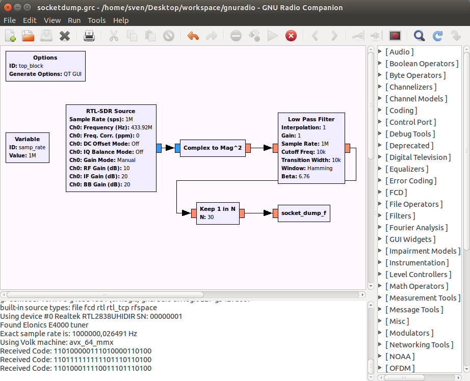
(The N=30 is just the first value I randomly used and then I build my module around.)
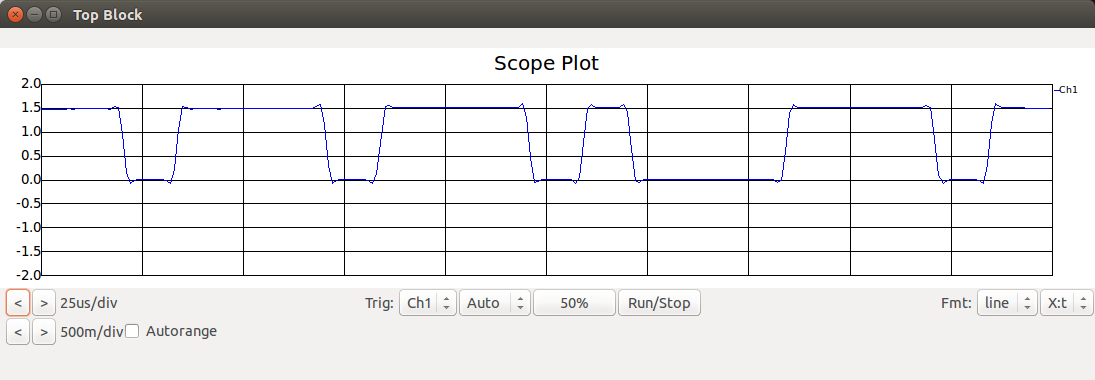
As mentioned, attaching a scope gives a little insight on what is actually happening:
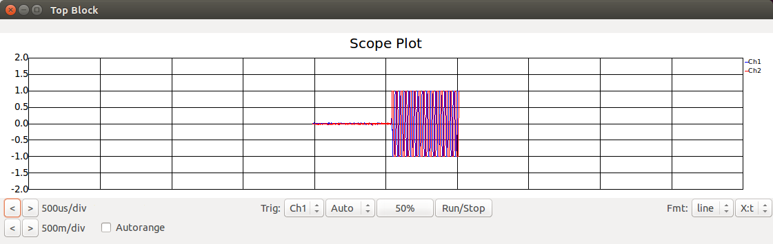
Scope attached to the SDR:
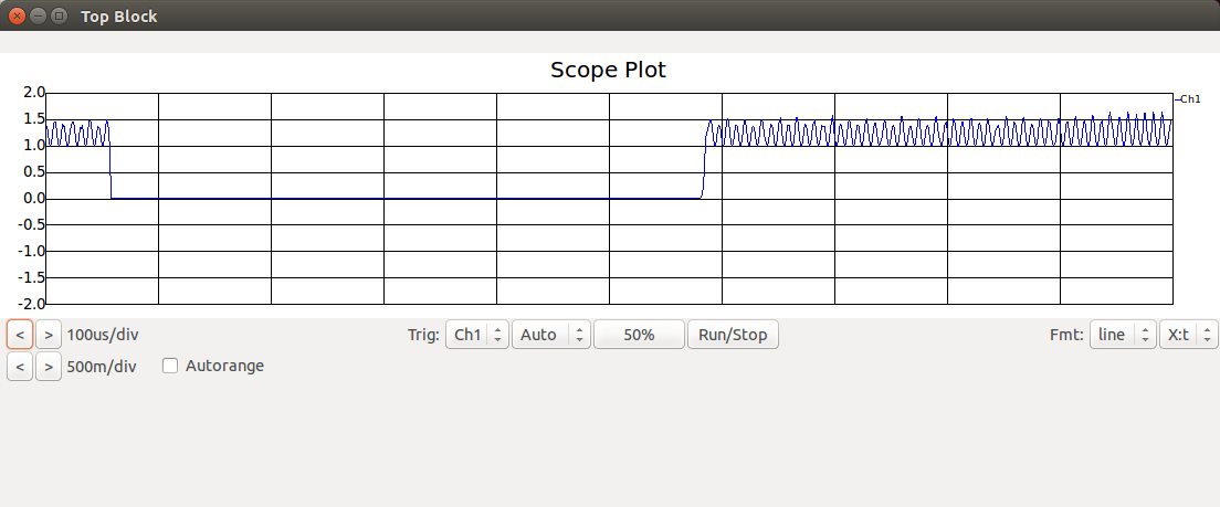
Scope attached to Complex to Mag^2 block:
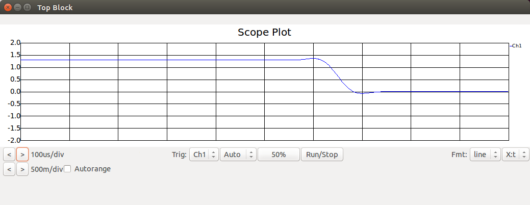
Scope attached to the Low Pass Filter block:
Scope attached to the Keep 1 of N block:
The python code for my socket_dump_f module counts 'streams' of zeros or ones.
A lot of 1s mean that this was the burst that separates the original signals. I store a 'X' for that.
Many 1s do represent a binary one in the output code.
A few 1s do represent a binary zero in the output code.
So I store CODE X CODE X CODE ... into a string.
If I detect a long row of incoming zeros, I assume that if there was a packet, it is finished.
If my string has some data in it, I split at the 'X' and take some code from between. Not nice, but good enough for now.
The code for the module:
#!/usr/bin/env python
import numpy
from gnuradio import gr

class socket_dump_f(gr.sync_block):
    """
    docstring for block socket_dump_f
    """
    def __init__(self):
        self.zero_counter = 0
        self.one_counter = 0
        self.last = 0
        self.output_buffer = ""
        gr.sync_block.__init__(self,
            name="socket_dump_f",
            in_sig=[numpy.float32],
            out_sig=None)

    def work(self, input_items, output_items):
        in0 = input_items[0]
        for item in in0 :
          if item < 1 :
            if self.last >= 1 :
              if self.one_counter > 50 :
                self.output_buffer += "X"
              elif self.one_counter > 20 :
                self.output_buffer += "1"
              else :
                self.output_buffer += "0"
            self.one_counter = 0
            self.zero_counter += 1
            if self.zero_counter > 1000 and len(self.output_buffer) > 10:
              a = self.output_buffer.split('X')
              if len(a) >= 2 :
                print "Received Code: " + a[1]
              self.output_buffer = ""
              self.zero_counter = 500
          else :
            self.zero_counter = 0
            self.one_counter += 1
          self.last = item
        return len(input_items[0])
If you want the module available in gnuradio-companion, you need some kind of xml manifest.
sockethack_socket_dump_f.xml
  socket_dump_f
  sockethack_socket_dump_f
  sockethack
  import sockethack
  sockethack.socket_dump_f()

		in0
		float
Last steps and open questions
There are 24 bytes:
[0-3] Something like a product family id? (always the same)
[4-19] Mystery-Code
[20-23] Button-ID (always the same for a on/off button pair)

* There are 8 different mystery-codes in total.
* Those 8 can be matched into 2 groups (A/B) of 4 codes.
* Either the on button takes codes from group A and off from group B, or the other way around.
Once a find a bit time, I will do some experiments with the sockets to see if I can uncover some more insights via active testing.
Questions, suggestions or feedback? Please let me know.
Talk to me
IT-Dienstleistungen
Drostestrasse 3
53819 Neunkirchen
Germany
USt-Id-Nr.: DE203610693
web: https://beastiebytes.com/
email: sven@beastiebytes.com
skype: sven2342
phone: +49 22 47 90 80 250
mobile/signal: +49 157 3131 4424
xing,
google+
OTR-Fingerprint: 7849BD93B65F9E4BC1206B06C09B7445721063BC
GPG/PGP-Key: (pub 4096R/069DD13C 2014-02-13) local copy pgp.mit.edu
GPG/PGP-Key: fingerprint: 9BAD 94D3 9176 5BD1 F64F 542E 37E4 3542 069D D13C